need some assistance with a nissan leaf power wall build

Ryan Gunner

New member
Joined
Sep 2, 2017
Messages
12
hey guys,

i'm planning to build a powerwall with nissan leaf battery modules. the following is my plan of attack for the battery pack itself.


image_ozvowe.jpg


what do you guys think about the arrangement and choice of breakers, cell fuses, dcfuses, etc.? do you recommend better stuff or i do something differently?

my typical load won't exceed 2000watts as this is only meant to power my home-office and not the whole house. i don't plan to use a bms for a while until i can save up some cash for a batrium.

i do have some questions i haven't been able to sort out myself. please see if you guys can help me out with these.
  1. if using twisted (with a vice and drill) copperwire for busbars, how do i calculate the thickness/ gaugeneededfor a system this size?
  2. what settings do i use with the PIP/MPSolar inverter to keep my pack from falling below 21v and going above 24.6v.

    for example, what do i set for the following:

    - bulk charging voltage
    - floating voltage
    - low dc cut-off voltage
    - back to utility voltage
    - back to battery voltage

    i do understand the first 3, but what exactly does the last 2 settings mean?

    and i know float charging is not suitable for li-ion batteries. so, is it not possible to disable the floating stage on PIP inverters?
  3. is there any budget friendly (probably off ebay) solution that can terminate the charging current from the inverter to the pack if any of the 6 cell-group voltages go above 4.1v? cause i'm thinking if one group becomes faulty (lose voltage but still conducts current), the rest of the groups will go above 4.1v to compensate.
thanks for any and all advise you guys can provide. i've already learnt quitea lot from your posts and yt videos. much appreciated!

good day!

cheers,
ryan.
 
I could be and probably am wrong by on a leaf cell isn't the middle terminal neg outside two are positive?
 
No the leaf 'cells' actually contain two cells, the middle terminal is the common point where both join. Outside terminals are positive of one cell, negative of the other.
 
RyanGunner said:
hey guys,

i'm planning to build a powerwall with nissan leaf battery modules. the following is my plan of attack for the battery pack itself.


image_ozvowe.jpg


what do you guys think about the arrangement and choice of breakers, cell fuses, dcfuses, etc.? do you recommend better stuff or i do something differently?

I use HRC fuses -https://www.amazon.com/shop/hbpowerwall they seem to be very good, I really need to buy more.

my typical load won't exceed 2000watts as this is only meant to power my home-office and not the whole house. i don't plan to use a bms for a while until i can save up some cash for a batrium.

Batrium have bolt on option for you :)

i do have some questions i haven't been able to sort out myself. please see if you guys can help me out with these.
  1. if using twisted (with a vice and drill) copperwire for busbars, how do i calculate the thickness/ gaugeneededfor a system this size?
Can't help there sorry
  1. what settings do i use with the PIP/MPSolar inverter to keep my pack from falling below 21v and going above 24.6v.

    for example, what do i set for the following:

    - bulk charging voltage
    - floating voltageSetup to the same voltage - low dc cut-off voltageThis is used to turn off system when offgrid - back to utility voltageThis is used to go from battery to grid when conected to grid - back to battery voltageBack to battery voltage is just that you could set it to 22v or fully charged up to youi do understand the first 3, but what exactly does the last 2 settings mean?and i know float charging is not suitable for li-ion batteries. so, is it not possible to disable the floating stage on PIP inverters?
It is not a lithium charger and you HAVE to remeber that configuring it to 'safe settings' & run bms naturally PIPS are NOTTTT ment for lithium - AGAIN... NOT !
  1. is there any budget friendly (probably off ebay) solution that can terminate the charging current from the inverter to the pack if any of the 6 cell-group voltages go above 4.1v? cause i'm thinking if one group becomes faulty (lose voltage but still conducts current), the rest of the groups will go above 4.1v to compensate.
thanks for any and all advise you guys can provide. i've already learnt quitea lot from your posts and yt videos. much appreciated!

good day!

cheers,
ryan.
 
1. 3kW nominal and max is around 6kW. I would set the busbars to handle 2x what the fuse is atleast! In your case lets say it can do 6kW as max then i would go with atleast

6000/22 = 270A max current and nominal is half so thats 135A. You would then need for normal atleast 8*2.5mm2 if you do like I do. If you want to be able to do max current and not much drop you need 16*2.5mm2. Its rather alot of current on 24V system yes! There is a reason why many go 48V.

2. Settings on your Inverter and charger is what you stated. Set it to the volt you want to limit as max and min. Set bulk and float to the same voltage to disable float kind of.

3. Doubt there are. If you spend this much money (If you didnt get above for free) I highly recommend that you go with a proper BMS and shunt trip that can protect them... Other wise with bottom balance you WILL some day over charge a pack or 2. Yes you can monitor it manually but shit happens to us all :)

50A on the battery isnt much at all... You wont get more than 1100W out of that fuse on the 24V setup and that is maxing the fuse out totally :) Dont forget to do 2kW continous and max up to 6kW that the inverter is made for you need thick thick cables :)

HRC fuses as Peter said is really nice ones.
 
2. Back to grid is the voltage that when reached, the PIP stops using the battery, goes to line mode and starts charging the batteries using grid power.
Back to battery is the voltage that when reached (and conditions are right) will stop using line mode and start using the batteries instead.
Mine are set to 23V and 27V respectively which allows me a safety margin for both up (29.2V) and bottom (21V) limits in case a pack or 2 become rogue (no BMS for the moment).
 
hbpowerwall said:
Batrium BMS has LeafMon for those cells

i'm actually not that concerned with top balancing atm. mostly because i can't afford a batrium starter kit yet :p

hbpowerwall said:
I use HRC fuses they seem to be very good

thanks for that tip. will check em out...

hbpowerwall said:
PIPS are NOTTTT ment for lithium

yes i get that. but it should be ok to use a PIP without a bms until i can afford one by keeping a close eye on the voltages right?

daromer said:
You would then need for normal atleast 8*2.5mm2 if you do like I do. If you want to be able to do max current and not much drop you need 16*2.5mm2.

i see... it's gonna be a really thick busbar then :)

daromer said:
Set bulk and float to the same voltage to disable float kind of.

hopefully when bulk and float are the same value, the charger should think that it's already achieved the float limit and turn off or drastically reduce the current right? has anybody tested this?

daromer said:
If you spend this much money (If you didnt get above for free) I highly recommend that you go with a proper BMS and shunt trip that can protect them

well, the battery modules are kinda free cause my leaf is scheduled to get a brand new replacement from japan in the next 6 to 8 months. my current soh/ capacity is around 57% and when it drops to 50% i'll use it for this power wall.

daromer said:
50A on the battery isnt much at all... You wont get more than 1100W out of that fuse on the 24V setup

i was under the impression that these fuses blow at around 2x the rated current. maybe i'm mistaken?

silverse2m6 said:
Back to grid is the voltage that when reached, the PIP stops using the battery, goes to line mode and starts charging the batteries using grid power. Back to battery is the voltage that when reached (and conditions are right) will stop using line mode and start using the batteries instead.

thanks for that explanation. couldn't find anything useful regarding this in the manual. appreciated!!!

thanks everyone for your help. greatly appreciated... keep up the good work and have a great day... cheers!
 
Some fuses blow at more than the rated current but 2x current is for very short time. If you say you going to pull 2kW continous EVERYTHING on that setup need to be dimensioned for it. And since the inverter is capable of 3kW continous and like 6kW max I highly recomend that you build the system to cope with what the inverter will do.

Think 2 steps ahead. Because when you have it up and you built the system for max 50A from the battery you need to swap out everything to go with what the inverter can do.

Everyone here on this forum that run lithium to the inverters have float and bulk to same or close to same. I have my float to 0.1V below bulk and that works great.

Btw imagine that you start a motor or something that is continous 1.5kW.... That one will take 5kW on startup and you will blow the fuse or the inverter will go in failsafe because of to high drop :)
 
daromer said:
everyone here on this forum that run lithium to the inverters have float and bulk to same or close to same. I have my float to 0.1V below bulk and that works great.


does setting it 0.1v below bulk make it never enter the float stage and end charging after CV stage? what is the behavior you see?

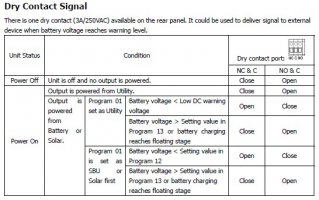
also could we possibly use the "dry contact signal" to detect when float charging is activated and use an external relay to disconnect the battery?

the manual says the following:


image_uesjhx.jpg
 
it will enter the float stage for a minute or 5. its just a way to top it off. Im not sure if this will help or damage but it works and i left it like that.

Why do you want to disconnect the battery when bulk is done? What use is the battery then ? :)

As long as the charger enters float and bulk it will after that stop charging. Thats normal on most chargers and works like that on the MPP products i currently have. Since i have current load on the system the batteries will never care of what is going on since they either charge or discharge kind of. They dont rest much :)
 
Ryan Gunner said:
well, the battery modules are kinda free cause my leaf is scheduled to get a brand new replacement from japan in the next 6 to 8 months. my current soh/ capacity is around 57% and when it drops to 50% i'll use it for this power .....

Is that a warranty replacement you are expecting ?
 
Fuses are supposed to be rated approx 20% above steady state load.
They have "time to blow" curves for different currents above their rated current - higher the current, shorter the time to blow.
Ie they are designed to handle short bursts like a motor start, etc without blowing but will actually blow if that high current was sustained.

If you uses fuses with peak load, the wiring or other parts would probably blow/melt/catch fire "to protect the fuse" (industry joke but serious issue).

+1 you should go 48V.
+1 get a BMS sooner rather than later.
 
Hi Ryan,

I have experience in using the leaf modules in a self build system.

You could use a voltage monitor like the JLD404 that ha 2 relay outputs, you could program it so that it shuts off the battery at your high voltage set point, as an emergency shut off, then add in a switch so that in the event of an emergency high volt shut off the battery has to see amanual intervention form you, to ensure all is in order with the battery.

The nissan leaf cells dont drift out of voltage too much, they stay pretty much in balance, just ensure your inverter parameters are well inside the leaf cell module parameters.
I think the leaf charger to a max V of 4.14, and they discharge to 3.5v, if no bms then id run a healthy margin nside those parameters too to ensure the cells dont run away from you.
 
Back
Top